Robot Arm Part 3: Electronics
In the last post I integrated the 6 servo robotic arm with the rotatable platform. In this post I will describe the steps required to connect the arm's electronic components together.
Installing the electronics on the arm is a simple process. The only process required is hooking up the different components to each other using the right ports and connectors.
Components
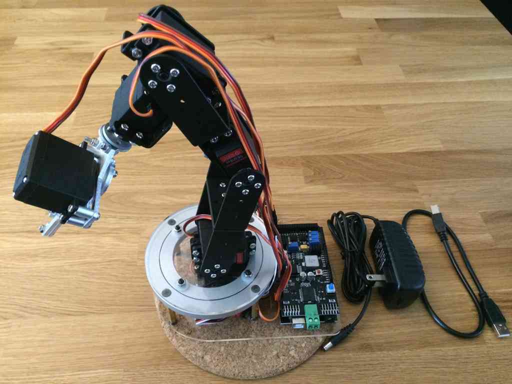
Here is an image of all of the electronic pieces. In addition to the six servos, the only other electronic pieces are the Arduino and Arduino servo shield, the 2.4Ghz radio module, the 12V power supply, and the USB cable.
Arduino Servo Shield
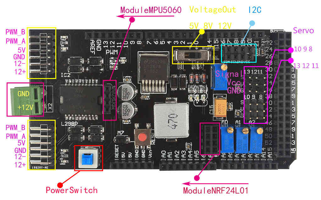
Here is a diagram of the Arduino servo shield used on the arm. This has been the only documentation I've found about the board. Based on this diagram, the functionality seems straight forward.
Power
As I mentioned in the component section of part 1, the Arduino servo shield requires a 12 volt DC power input in order to power the servos. The servos are not able to use power from the USB input from the Arduino. This is done because using multiple servos would draw too much power from the Arduino, risking damage to it.
I am using this 12V at 0-2A AC to DC power plug to supply the servo shield.
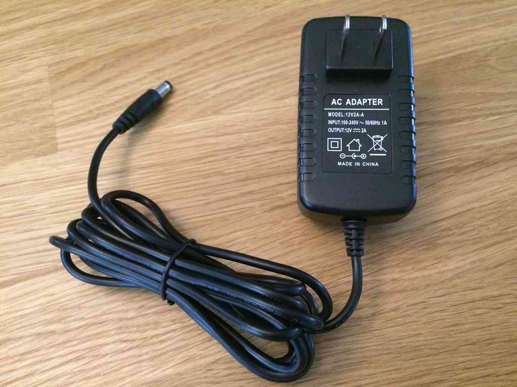
You will note that this power plug has a standard DC plug at the end, however, the servo shield has no receptacle for it. The servo shield has a direct power connector (the green piece) where wires can be inserted and screwed down. In order to work with this, I clipped off the end connector and stripped the wires so that they could be inserted into this receptacle. Take note of which port is for the voltage and ground wires!
For a more flexible solution, a variable DC power supply like this Tekpower 0-30V at 0-5A power supply would easily handle the job. In addition to allowing you to monitor the exact power draw of the arm, you could use the supply for many more projects in the future.
I have not tested the exact power draw of the servos and electronics, but the 2A power plug should be able to handle it. Each servo should draw a little more than 200mA, and the Arduino Mega draws much less than 200mA.
Servo Connections
The servos are connected directly to the Arduino servo shield. They need to be connected to the right number in the right orientation to ensure they work with the code I'll build later.
Servos cables have a specific orientation required when being plugged in. The servo cables include a ground connector (G), a 5V power connector (V), and a signal connector (S). Normally, the ground cable is black or brown, the voltage cable is red, and the signal cable is either white or yellow/orange.
Here is the structure I used when connecting the servos to the ports:
- Waist servo to port 8
- Shoulder servo to port 9
- Elbow servo to port 10
- Wrist elevation servo to port 11
- Wrist rotation servo to port 12
- Gripper servo to port 13
Another important aspect is to check the output voltage for the servos. The switch near the servo ports allows you to change what voltage is being sent to the servos. The servos included with the kit can only handle up to 6 volts. Thus, only the 5V option can be used. The more voltage used, the more torque the servos will provide, however, too much voltage will damage the servos.
RF Module
The 2.4Ghz wireless module will allow the controller to connect to the arm wirelessly. The wireless module connects directly into the servo shield.
Complete Electronics
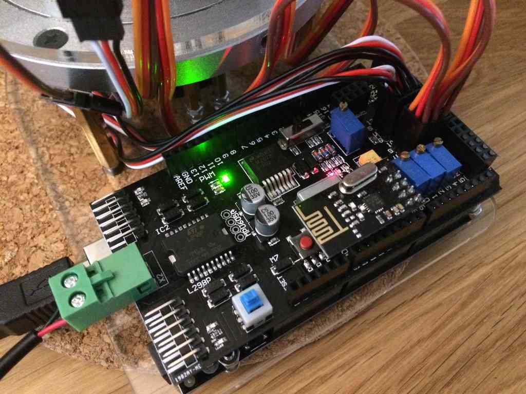
Here is a picture of the fully hooked up electronics. The servos, DC power, USB and wireless module are all connected and powered up.
Read the next part here where I document the steps to build the Arduino Uno based controller that came with the arm kit.