Robot Arm Part 6: Advanced Code
After a three year hiatus, I have finally(!!) completed the code that allows an Arduino Uno based controller to wirelessly control the Arduino Mega2560 based 5 DoF robotic arm. If you are new here, you can start the robot arm series at part 1.
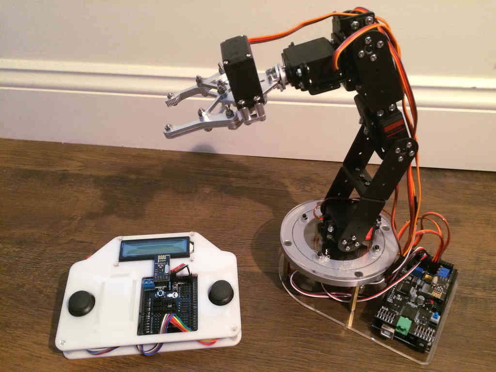
As a quick recap, I built a simple 5 degree of freedom (DoF) robot arm that was based on 6 low power servos connected to an Arduino Mega2560. A separate Arduino Uno controller contained two X/Y joysticks and a 16x2 LCD screen. Two nRF24L01+ chips allow wireless communication between the two Arduinos. The challenge (and why it took me so long to write this post) was writing Arduino capable code for transmitting commands from the controller to the robot arm. After dedicating a few weeks to this and reading the amazing guides at Last Minute Engineers, I have developed code capable of providing this.
Code
You can access the open source code here. If you want to duplicate the same development environment, I recommend you use VSCode and PlatformIO. PlatformIO handles complex Arduino projects better than native Arduino IDE. This is important for this project because it is using two Arduinos.
While the code environment will require some modification for your specific system, the core controller and robot arm code can be migrated elsewhere. Contact me or raise an issue if you have any questions.
Process
Controller Input
The Arduino Uno controller uses two X/Y joysticks for control input. A noise processing check ensures that only actual joystick movements are processed, and not potentiometer noise or joystick misalignment (a common feature of check joysticks). The analog signals are converted into a byte, and packaged into an array for transmission to the robot.
Data Transmission
Wireless communication is handled using the nRF24L01 chip, which is a 2.4 Ghz transceiver (transmitter and receiver) on a small circuit board. It allows two way communication utilizing the SPI bus. View the link above that provides an excellent overview.
I used the RadioHead library for interacting with the radios. In the end, I used a UDP style approach, where the transmitter did not need to wait for a receipt confirmation. The controller only waits 1 millisecond before sending the next transmission. I determined that it is more important to stream the current commands to the robot than to receive individual command confirmations. This provides a more fluid control experience due to shorter latency between human input and arm movement.
The robot arm continually seeks new data. When a new packet is received and buffered, an error check ensures the value is between expected ranges, and converts the byte into a movement delta. The delta indicates how much a servo should move, with a higher number indicating more movement.
Robot Movement
Based on the movement delta, an error check ensures the command keeps the servo within its operational range. Some servos (like the shoulder rotation) can rotate through their full range, whereas others (like the end effector claw) have restricted movements.
If the movement is valid, the movement delta is added or subtracted from the current servo angle. All movements are processed before the actual movement command is given. The current code commands the servos using microseconds instead of angles, giving the servos higher definition movements.
Controller Feedback
After processing the arm movement, the arm transmits its status back to the controller. These are the commands received while the controller waits the 1 millisecond after sending movement commands.
The feedback information allows the controller to know whether it has a live connection with the robot, along with key servo angles (converted from microseconds to angles for readability). See the controller display section below for more details. Currently, this data is only used to inform the operator, and does not impact system operation.
Hardware Update
I started this project utilizing the electronics Sainsmart provided with the system, including an Arduino Mega2560 and a Sainsmart exclusive servo shield. The servo shield provided a convenient way of plugging all 6 servos to the Mega2560, along with a ready to go plug for the nRF24L01. The board also had a 12 volt power plug, allowing an external power source for powering the servos.
However, all PWM servo signals were not offloaded to a separate chip, being processed by the Mega2560 itself. If no other tasks were being processed, this would be fine. But this system requires the nRF24L01 to actively listen and transmit signals, via an SPI interrupt. The interrupt caused inconsistencies in timing for the PWM signals used for the servos, causing severe jitters for all servos. This could be mitigated by disabling the servo signal pins (setting them to `INPUT`), but this didn't fully solve the problem. The solution was to use a separate chip for PWM signal generation.
The PCA9685 I2C PWM Driver provides the solution to this issue (you can get three non-Adafruit PCA9685 boards for half the price). The I2C bus allows connections between this board and the Mega2560 (or any Arduino or Raspberry Pi). Each driver allows you to control up to 16 servos with no stutter. A dedicated 6 volt DC power input provides power to all servos. Just make sure your power supply can provide enough current (2 Amps should be sufficient, but spikes could be higher).
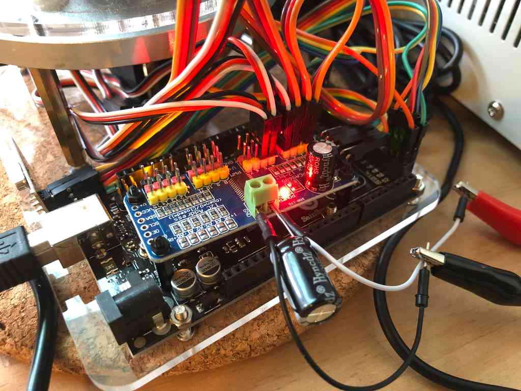
The image above shows the six servos plugged into the PCA9685 board on pins 0 to 5. Notice I used a large capacitor across the DC power input. This smooths out the current when a servo is changes speed quickly. Make sure to not exceed 6 volts on this board (although Adafruit says you can supply 12 volts, it poses a risk of damaging the attached Arduino if you short the wrong pins).
If you do use a PCA9685, you will not be able to use the standard Servo library. Instead, you will need to use a PWM based servo library, like the Adafruit PCA9685 PWM Servo Driver Library (this will work with any PCA9685 driver). This library is NOT a drop in replacement, and requires some code modification. My current robot code utilizes this library, so use it as an example. You can also watch this excellent servo video that shows the basics of using the PCA9685.
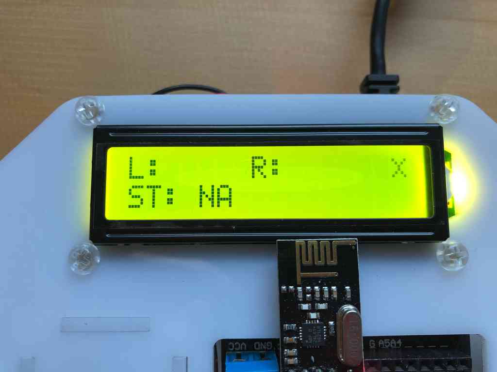
Controller Display
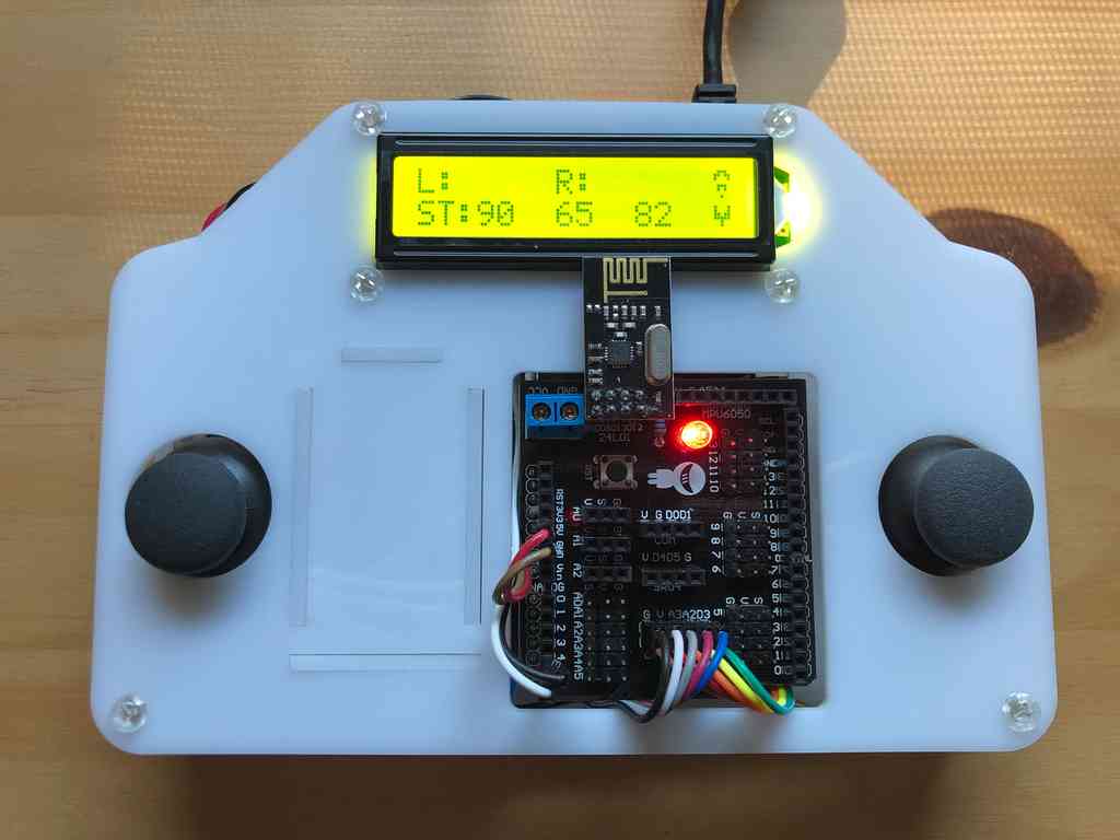
The LCD display allows for two rows of text, each 16 characters long. The top row rows the direction each joystick is actively angled at, along with a signal icon indicating whether the controller is connected to the robot or not. The bottom row shows the current servo angles and status of the end effector claw (open or closed).
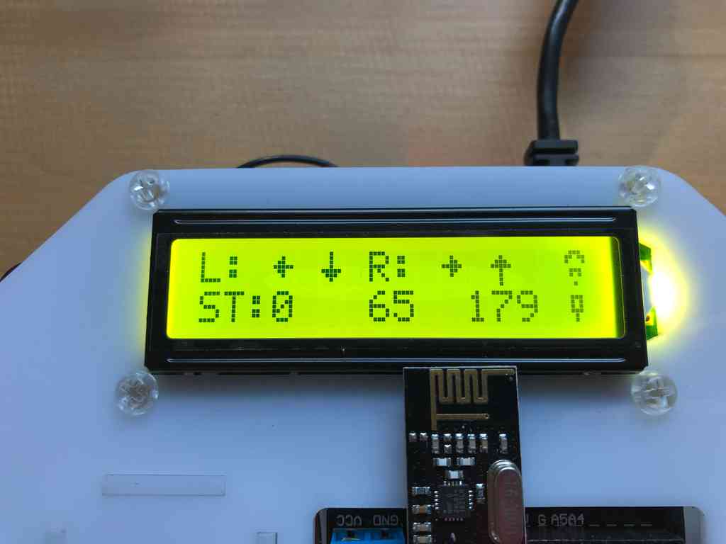
When the connection fails between the controller and robot, the display shows an `X` in the top right, along with a status of `NA`. The top row joystick indicators still works, however.
Conclusion
This concludes the multi-part series on the simple robotic arm. I covered the build process for both the robot arm and controller, along with a simple code example and an advanced code setup.
This is a good point for integrating the robot arm into ROS (Robot Operating System), allowing you to automate control of the arm. Examples include having the arm automatically find and pick up an object next to it, or having the arm track an object utilizing a camera attached to the end effector. Ultimately, the sky is the limit (well, maybe the hardware will limit you first...).
If you do something cool with this code, or want to share your own project, please contact me. I'd love to see what you build!